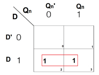
K Map For D Flip Flop – A D (or Delay) Flip Flop (Figure 1) is a digital electronic circuit used to delay the change of state of its output signal (Q) until the next rising edge of a clock timing input signal occurs. The . Regarding it, I have a doubt about its output state during power up. In this configuration for the D-Flip flop, the clock signal is given by Shut down_TTL. It is held at logic low after powerup till .
K Map For D Flip Flop
Source : www.youtube.com
Conversion of J K Flip Flop into D Flip Flop GeeksforGeeks
Source : www.geeksforgeeks.org
D Flip Flop Circuit, Truth Table, Limitations, and Uses
Source : www.electronicsforu.com
K map Simplification and Excitation table for D Flip Flop | Telugu
Source : www.youtube.com
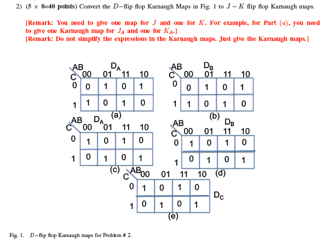
Solved 2) (5 x 8–40 points) Convert the D flip flop Karnaugh
Source : www.chegg.com
digital logic drawing flipflop after statement table and kmap
Source : electronics.stackexchange.com
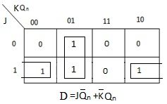
D flip flop state equation for given k map
Source : www.careerride.com
digital logic Finding functions for JK / D / T flip flops
Source : electronics.stackexchange.com
JK Flip Flop, SR Flip Flop using D Flip Flop
Source : electrosome.com
digital logic drawing flipflop after statement table and kmap
Source : electronics.stackexchange.com
K Map For D Flip Flop D Flip Flop || Block Diagram || Characteristic Table || K Map : That covers everything you need to know about codes for Flip Flop Simulator. On a side note, if you do enjoy idle experiences like this one, then you should definitely try out Pixel Incremental 2. . Choose from Flips Flops stock illustrations from iStock. Find high-quality royalty-free vector images that you won’t find anywhere else. Video Back Videos home Signature collection Essentials .


